Saturday, August 31, 2013

Sacrilege??

Over a year ago, when I embarked on the sound deadening project I had bought several spray cans of this:


Looking at reviews online in Japan, this product (the "Beat-Sonic Noise Reducer") was generally acknowledged as the best, not only in sound dampening ability, but also as a general undercoating (to prevent rust) in cars.

Luckily, as they don’t use salt on the roads in the winter, and also because I frequently wash my car, there are very, very few spots of rust on my car.  The few spots that I have spotted were surface rust on the car when I first bought it (mostly easily removed), and I haven’t seen any new spots since.  So really, there really is no need to apply an undercoating, so long as the car is in Japan and relatively well maintained.

Here is the worst of the rust.
I was hesitant to spray this on for a few reasons – one obviously is weight, but the other was, would this material be removable in case there was a spot of rust that got out of hand and that panel had to be repaired?  Again, is it really necessary for me to do so?  Sacrilege to unnecessarily paint my car??

In any case, I thought I reached a happy compromise by deciding that I was going to spray ONLY on the inside of the fenderwells, behind the wheels, where I suspect most of the road noise was getting through (because the floor had been lined with the sound deadening material already, on the inside) AND because I planned to spray the stuff ONLY on the plastic fender liners.

So, I jacked up the car, took the wheels off, then liberally sprayed on some Simple Green to break down any dirt there.

And yes, I also took the opportunity to clean the wheels, especially on the insides where there was some brake dust.
Hard to clean as those calipers leave only a few millimeters of space


Oh, and yes, what a great opportunity to clean the R35 brembo calipers!
This dirt had been bothering me for a long , long time...

Ahhhhhh....
I then used my trusty Vapamore steam machine to REALLY get things clean.

Before:

After (and after I started wrapping with newspaper):

I then covered up all the important components with newspaper, and began to spray on the undercoating.  But then realized that, I might as well go for the metal too (which, I believe, already has a CLEAR looking (but now yellowish) factory undercoat in some places)

So here is how it looked after spraying on the undercoating.  In addition to rust protection and sound deadening, I realized then of another advantage – of making the inside of the wheelwells look dark, thus enhancing how the wheels look.


And the result? Nice and CLEAN and BLACK....lol.  Oh, and also as the pitted plastic liners are now covered with the deadening, hopefully they will be easy to keep clean now.

As to whether the coating had an effect on road noise, in my judgment, "yes" but only slightly. Then again with the Tomei Expreme exhaust uncorked, it was a bit hard to "hear" the difference over the exhaust note, but during the Izu Skyline run, it just seemed that under some circumstances, the car DID seem to have a bit less road noise...

The background is all black....

Wednesday, August 28, 2013

Speedhunting: Izu Skyline Drive with Friends


This year, I have been too busy to take my car out on a proper drive. Lots of minor tinkering, yes, but not a chance to really enjoy the car for what it’s built for.

This changed when my friend Dino proposed a short drive trip up to the Izu Skyline road near Hakone, ostensibly to try out his new tire and wheel combination, but we both knew the real reason was for all involved to de-stress from our daily lives.

Here is the link to his fantastic as usual Speedhunters post. He does a better job than I could of explaining the route we took and the scenery along the way, so I won’t bother to describe the trip (please read his post) and further I have taken the liberty to borrow these photos from his post:


So hard to take a decent photo of these brakes and the car, but I think Dino did it! Except the car looks grey...
As Dino mentioned in his post, the three of us, Thomas in his Midnight Purple BCNR33, Dino in his Bayside Blue BNR34, and myself, first met up at the Ebina Service Area off the Tomei.

Yes, Dino was late...
Hey look, those non-functional brake scoops actually work... kind of...
In addition, we met up with our friend Matt (BNR32 owner) who was on vacation in Japan and kindly agreed to meet us up there in his rented orange Z34 Fairlady. You can see it in one of Dino’s photos.

I also took some photos, but they were nothing special.  Matt had a decent camera with him and was kind enough to share his wonderful photos for inclusion on this blog. Here they are, and thank you again Matt!

Here is the entrance to the Toyo Tires Turnpike, which then leads up to the Izu Skyline Road!
At the top of the Turnpike, Matt was already waiting for us... here I am explaining to Dino that
Matt beat us up to the top...
From another angle...
Close up of my car while in the three car formation at the top of the Toyo Tires Turnpike. Yes, Thomas was driving in his beach sandals...
After the Tsubaki-line run, I kept going... into the town of Yugawara.  Here I am after I called the boys and re-met up with them where they were waiting for me...(Dino had to cool off his brakes anyway...)

Fantastic picture Matt! The lighting is sublime, I love how clean the car looks!
At the parking lot on the Izu Skyline. Just like the photos in Dino's Speedhunters post.
And here we are cooling the cars off... getting ready for Dino's mini photo-shoot.
So there you go... and for those of you who know me, yes, I was running a new "mod" which I will talk about in my next post. Stay tuned!

Tuesday, August 6, 2013

Wiring up the DIY Rear Diffuser LED


Continuing from my last diffuser post - the final step in the BNR34 rear diffuser project was to wire up the LED. So this is how I did it:

The LED unit itself has 3 leads coming out of it, labeled“+”, “-“ and “brake.”  The unit was described as having a“flashing brake lamp” a la F1 style, and my 12 volt tester confirmed this was the case.

In any case, the first step was to ensure that, should I have to remove the diffuser in the future, I would be able to disconnect the leads without having to cut any wires. So, I found and ordered 3 lead to 3 lead connectors, which I then soldered onto the ends of the wires coming out of the LED, as well as to 3 wires leading into the body of the car.

It ended up looking like this:
See the white connectors
Next, with the wires being exposed to the elements, I wrapped electrical tape around the leads, and also used some protective heat shrink tubing for the LED leads going all the way into the body.  There is a rubber grommet (which has other wires going through it too - most notably the back-up camera leads) covering a hole just above the license plate frame, so I passed the wiring and the heat shrink through this.

I then removed the rear seats, ran the wiring alongside other wiring, zip-tying strategically, and then routed the wire to underneath the center console.  I soldered on some connectors (one side the wires from the trunk, the other on the wire leads going to the switch), to allow for complete removal of the center console when necessary, and then ran the connecting wiring through the pre-existing hole that I had drilled for the ATTESA controller that never worked right for me. I made sure I used connectors, so if I ever need to remove the console, I don't have to cut any of these wires.


On the trunk side, because the wiring into the car ran on the left side, I opened up the rear left side light cover to access the wiring there.  I then cut two short pieces of wire, and soldered the ends of both to a two lead connector.  On the other end, I soldered one wire onto the lead for the running lamps (there was already two wires soldered together on the factory harness for the two left rear lights, so I simply soldered on top of that, rewrapping in electrical tape), and then used a tap for the other wire, which I connected to the brake light wire.  This two lead connector was then attached to the two lead connector for the two wires coming BACK from the main cabin. So now I had one long connection going from the bulbs to the center console. I used clips throughout, in case in the future I want to remove part of the circuit but keep other parts, with no cutting required.

For the lead coming from the LED unit, I soldered a connector to the ground wire and bolted it to the body. The remaining two wires - one being the positive lead for the running lamps and the other for the brakes - I ended up also soldering leads for connectors, to be mated to the appropriate connector for the wires leading to the main cabin area. So this was the other long connection, going from the LED to the center console.

So, I now had a complete (fairly long) circuit, broken only by a lack of a switch connecting the two leads coming INTO the cabin from the LED unit itself, and the two lead going OUT into the cabin to be wired into the brake light circuit.   Initially I had envisioned have one switch handling the ground wire only and serving as a master on/off switch, but then realized that I wanted independent control of the braking and the running lamp circuits, as the flashing red lamp clearly violates Japan’s shaken (road-worthiness) laws.Thus I ended up sending 4 wires into the cabin (2 in, 2 out).
Here is the harness I made, open leads (4) to connect to the switch, the clip inserts into its mate underneath the center console
Given the need to be able to quickly toggle the LED on/off from within the cabin itself (i.e. remember this mod likely is illegal on public roads), I spent some time looking for various switches which would work. Initially, I was set to use these tiny switches, with one switch being for LED to come on with the running lights, the other switch being for the LED to be wired into the brake circuit.  

The problem, however, was that I now had the problem of how to affix these switches to the center console.  Do I carve out two holes directly? Or do I have some kind of bracket? Where would I locate them? Should they be visible? Or do I install in a hidden spot?

In the end, I finally decided that something that looked or was, OEM would be my best bet.
I found this on Yahoo Auctions - it is the switch for the OEM Nissan optional foglights,
as our
 red R33 friend Miyuki-san demonstrated. 
But rather than placing this switch next to the GT-R logo where it is normally placed:

I decided to continue with the stealthy scheme and install inside the console.  So this required some cutting of the center console for the switch to fit.
The center console, as seen from below - I had to use a drill and drill several holes
as the angle was wrong for the Dremel!
And then use a very sharp razor knife to make nice and clean
Then, I discovered that while the switch fit perfectly, the switch itself was too tall, meaning I had to cut off some of the bottom of the switch, and also bend the leads on the wires so they could connect to the switch with minimal amount of wiring sticking out of the bottom vertically, where it was bumping into the G-sensor.

Used the Dremel here!

Note how the leads are bent 90 degrees
The end result, however, looks fantastic, is solidly mounted and is hidden.
Actually it looks here like it's lifting up a bit, but in reality the switch is flush
with the floor of the console box
Anyway, it all works perfectly in the end - here is a video showing the LED lamp in action: First, just the running lamps, then turning the switch on to get the running lamps plus the LED, then the brakes with the LED (see how it flashes), then release the brakes, then turn off the LED.


So now all that's left to do is see how the diffuser performs at speed...

Thursday, July 25, 2013

HID Rear Fog Lamp, NOT a Good Idea

So I recently outfitted the car with an HID back up bulb.  And, found out when doing this mod that, in fact the regular incandescent bulb was BRIGHTER than the LED bulb that had replaced it, which I then replaced with the HID bulb. My conclusion at the time was that the LED bulb was whiter or bluer than the yellowish incandescent bulb, but NOT brighter on the Lumens scale.  The HID bulb was whiter/bluer AND brighter than the LED bulb, so I decided to go forward with the install of the HID bulb.

At the time I had also compared the standard incandescent bulb and the LED bulb for the rear fog light - but it was obvious that the incandescent bulb resulted in a brighter, redder, light. Hence I kept the incandescent bulb in place.

But, while working on final rear diffuser mod, I decided to see what would happen if I took the next logical step of installing an HID bulb in place of the incandescent bulb for the rear fog lamp.  Here is the result.

Incandescent Bulb

HID Bulb
So again the regular incandescent bulb seems to produce the most light for a red lens, as used in the rear fog lamp.  I have to conclude that, despite the HID being "white" versus the yellow of the incandescent, either a yellow light produces more usable, visible light and/or for a RED lens, a whiter light behind a red lens does not always produce the brightest possible light. Or, perhaps an HID is directional and so works best if used in conjunction with a mirror lens surface that focuses the light in a proper way (like the headlights).

So the next step will be, researching the brightest possible incandescent bulbs! Stay tuned....

Monday, July 15, 2013

BNR34 Rear Diffuser Project, Part 5: Done!

While taking photos of the various pieces that had to be fitted to make the diffuser fit, I realized from the following photo, the rust on the leading metal edge of the diffuser really bothered me.

That, and I also realized that I was simply ignoring another problem, the rust on the inside fin mounts:

So off to the hardware store I went, searching for the Japanese equivalent of Rust-Oleum StopsRust, the paint that you spray on and which slows down the progression of rust (it was too much work to actually strip down all the rust and then respray). I couldn’t find a spray product, but did find something in a can that’s used for black iron fences, etc.


So, I took off the diffuser, and painted all rusted surfaces with this anti-rust paint in the hope that this would at least slow down the spread of the rust that’s already there. If of course it’s too late, well at least I have the stainless brackets and other parts from the RB Motorsports kit that can probably be used in their place.
Looks much better, right?
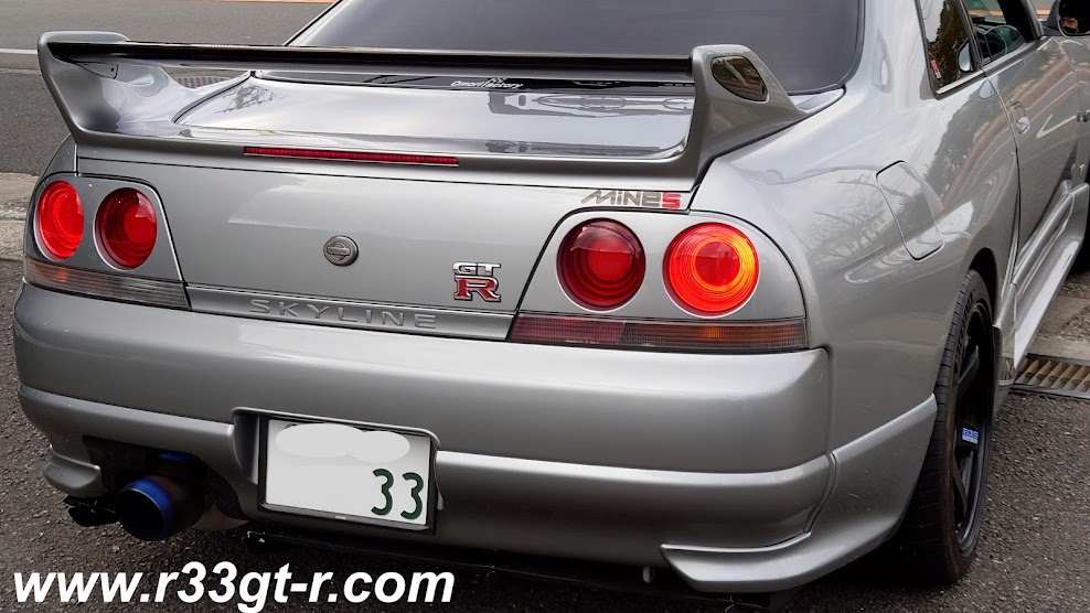
And, since I had the diffuser off, I decided to see if I could do one more mod.  I remember reading in GTR Magazine about a shop that installed a red F1 style rear LED in the center bracket, and found two examples on Minkara.  (Here's the other).

But, I’m not about to spend 34,000 yen (plus that was a limited edition run of 10 plus units) on this! So I searched on Rakuten and first found this:
Not bad at 900 yen, but the reviews were mostly all bad....
But given that the dimensions I could work with were:  about 6cm for the space between the body of the car and the diffuser, and about 3cm between the leading edge of the diffuser and the bumper, I found instead a rectangular one with better dimensions: 


Once ordered it quickly arrived - and though I'm sure it probably costs less than $5 in the US (and even less than that in China), unfortunately it was a bit more than that here...

So as you can see it had this clip attached to it. Initially I was not going to use this clip, but then decided that, instead of making my own brackets, it might be better to figure out a way to attach it using this clip – either to the car body or to the diffuser itself.


After some thought, I realized that to attach this LED to the car body would require new holes to be drilled, or the diffuser stays would have to be modifed.  It would probably be easier to attach to the LED light to the diffuser itself, so that's what I decided to do.

I found a stainless steel (so it wouldn't rust) bracket with holes, which bolted on nicely to the end bolts of the rear-most bolts of the two inside fins (which are spaced apart exactly 46 cm!) on the inside top surface of the diffuser (you can also see the formerly rusted inside fin mounts now painted black here too):

Then, using the clip that came with the LED light, I was able to test fit it by slipping it (temporarily) on like this:

I was envisioning I would be able to attach it all so it would be like this:


But I then realized that I had to do something to prevent the LED lamp and its clip from slipping off the stainless bracket - so I decided to use a "V" shaped rubber piece with adhesive on both inside surfaces between which I sandwiched the stainless bracket.  The two bolts shown here were then used to center the LED clip on the stainless bracket:  

So it ended up looking like this:

And then to prevent the whole contraption from slipping around and thus possibly falling off, used some silicon adhesive on the side that would contact the diffuser:

After I bolted this whole contraption onto the diffuser (again using the two rear-most bolts of the inside fins), I temporarily re-attached the diffuser to see how it would fit.
Looks pretty good, huh!
Now all that was left was to wire it up to the lights. This I'll cover in a future post, because it took some time to get right.   In any case - finally - here is the finished result, in day light! Comments, critiques, and questions most welcomed!