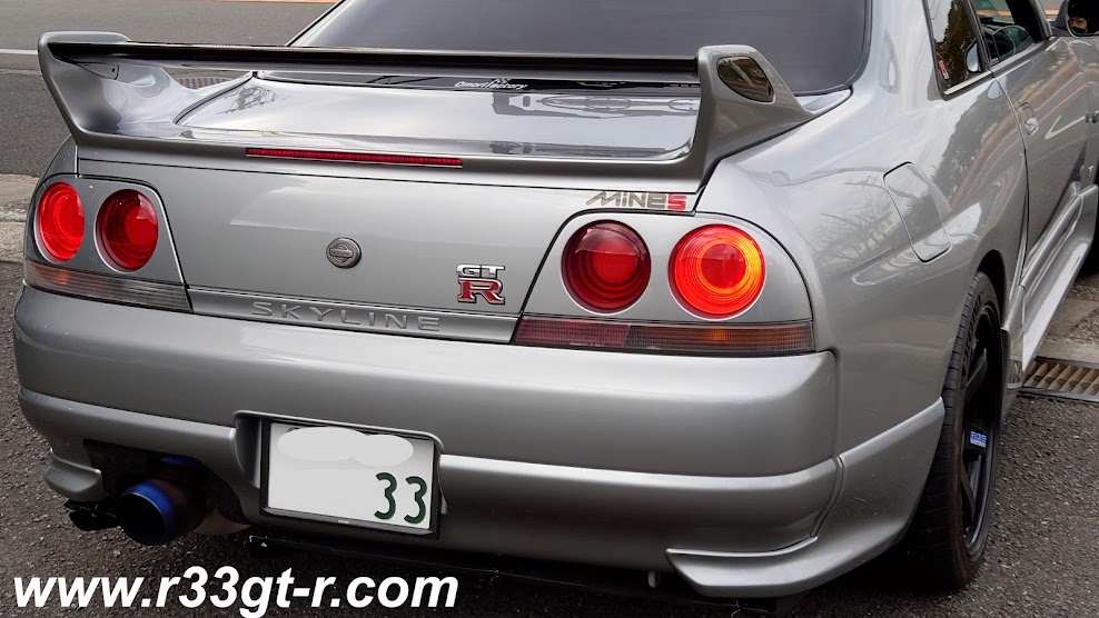
Showing posts with label WORX. Show all posts

Sunday, November 26, 2023

Removing My Most Annoying Mod Of Choice

 So after removing the crap car alarm and stereo that WORX Auto Alarm had installed in my car, I decided that without an alarm, I needed to figure out some ways to make my car harder to steal.

Enter the removable steering wheel idea.

This required changing the after market Daikei  boss I had installed several years ago to fit my steering wheel and replacing it with the WorksBell RAPFIX II wheel lock system.  

Installation was easy, but there was one problem - it moved the steering wheel a few centimeters closer to the driver, and in my case, made using the turn signal lever a bit of a stretch. Oh and given my short legs, I had to recline the seat to give my arms some space too. Anyway, it always felt unnatural.


It was a good idea otherwise, with removal of the wheel very easy - just pull on the silver tab (green arrow pointing) and the entire wheel unlocks due to the very clever mechanism - in essence a column side "male" steel column and the steering wheel with a matching "female" coupler.

Unlocked, it looks like this. And yes, WorksBell sells a steel cap that locks on top of this, with a key lock, to prevent thieves from walking around with their own steering wheel with the matching coupler. (I have one but no photos sorry...)

Anyway, I went into my cabinets and found the previous non-lockable/removable Daikei boss, along with the packaging for the RAPFIX II.


And then took the wheel up to the work bench, to begin the surgery.

Pretty easy actually. Just undo the allen bolts...
The female coupler on the right - note the wiring for the horn button

Next was to remove the steering column side coupler.

Again, super easy, just undo the allen bolts - here you can see the electrical coupler, along with the round metal ground between then column and the coupler.

And yes, this one was a bit of a struggle to remove. Despite using this breaker bar, I kept applying so much torque the front wheels kept moving on the epoxy floor...

Alas success was soon found, but it did cause me to wonder what I would do if I was unsuccessful in getting that bolt off...
Note the green arrow pointing to the resistor which came with the RAPFIX II - I removed it and put back on the resistor that came with the original short boss. This becomes important later...

This is a very chunky piece of aluminum...

So now, I had to reinstall the old boss.  And this time, I want to make sure I do not over or under torque. Enter one of my newest tools, a KTC electronic torque wrench!

I had picked it up a while ago but had no reason to use it, until this project!
Packaging is beautiful, as can be expected of Japan.


And yes, thanks for pre-charging this for me so I had no down time since I did not need to charge it up!

So the owner's manual gave a range, 29-39 N-m.
I decided to go on the higher side

Then it was making sure the wiring for the horn and the resistor isn't pinched.

The black coupler is for the horn. The resistor has been tucked underneath the sleeve that slips on over the boss.

And here is the metal plate that is needed to act as the ground for the horn button.

The Ital Volanti wheel fits nicely over this plate

Complete!

So it was super nice to get this back on - the wheel position felt natural, I could easily reach the turn signal stalk with my pinky finger, and my arm and seating positions felt natural again and not cramped. Nice!

Except... there was one small problem. The Airbag warning light kept flashing. I tried the driver's side door switch trick, yes, and even tried switching the resistor back to the one that came with the RAPFIX II. Nothing worked.  So guess who I called....

Saturday, September 30, 2023

Minor Electrical Issue Was Worth Fixing!

So you all will remember the nightmare that happened a few years ago when a rogue stereo /alarm installer decided he would use my car as his experimental test bed and not apologize for all the goofs? Well, one consequence of that was that a lot of the wiring harness got chopped and so many connectors on the harness were lost.

One of these was the connector to the cigarette lighter.  It's only 3 leads, but... And I recall it was because he had relocated the HVAC controls to this lower area, obliviating the need for a cigarette socket. Sure, I guess you then don't need the connector to the cigarette lighter but what if I changed my mind later?

Anyway, recently I realized I was having problems with this compact cigarette socket USB charger.  I would plug cables into it that I knew were not defective, but my phone would not charge.

Excuse the dust! Also, this unit is supposed to light up when power is flowing to it...

I would tinker with the backside wiring, and sometimes end up with the cigarette socket surround lit up (not the unit itself - it needs acc power) when the lights were off, and vice versa. Or no power at all, even when the engine was on.  Finally it dawned on me that this USB power thing might be broken. So...

24 hours later - Amazon to the rescue... yeah the box got crushed

But the unit inside was fine.

Bright red so I wouldn't get confused with the current one. Plus, anodized red is always nice

Obligatory comparison photo.

So what happened then? Obviously, a simple successful swap would not result in a blog post. 

Well both good news and bad. Good, in that as the red unit lit up, I knew the black unit had failed.


But bad, because it STILL wouldn't charge my phone.  The phone would recognize power being sent but the current seemed to fluctuate on/off/on/off/on/off... and then nothing. So annoying...

So it was removing the shift surround panel to access the wiring once again and...

And yes, the tape deck is working perfectly, and sounds awesome too!

I finally figured out that the wiring being inserted into the cigarette socket circuit was wrong, even though it was lighting up properly.  Actually, without the ignition on, turning the lights on gave a "buzz" sound so I knew something was off.  So I swapped some wires around and...

Proper wiring positions - for my records, just in case!

Success! Power to finally charge my phone.  I celebrated by buying a USB-C charging cable with both Lightning and USB-C ends to allow for charging of both of my phones (and anyone riding with me with an older iPhone).


So really just minor stuff. What's next? That reminds me I need to talk to Ochiai-san at Omori Factory...

Thursday, December 24, 2020

One More Item Back to Normal

In this case, I am talking about the control module for the Defi heads up display (no longer available, sadly).

I originally installed this gadget because I had initially kept the original speedometer, which only displays up to 180kph, per the old Japanese rules (and I think I did so when I first got the car, even before I started this blog!), rather than swapping out for a Nismo 320kph one. But I was literally seeing the needle go past the 180 mark and almost complete a full revolution every time I took the car to a track day at Fuji speedway. However, I didn't want the bother of swapping out the speedometer cluster because of the hassle in having it all re-registered with the new mileage (assuming you do it legally here in Japan).

As long as long time readers know, I eventually swapped out to a Mine's 320kph speedometer cluster I found, for which I had the mileage readjusted to be accurate to the car's accurate mileage.  And since I doubt I'll be selling the car to an unknown buyer later, paperwork to record that didn't seem that essential. Plus the photos on this blog serve as proof anyway. 

In this previous post, I found that Nakamura the owner of Worx Auto Alarm (stay away!) had HIDDEN the Defi control module OUT OF SIGHT so it could not be operated. In the kickpanel, people! Obviously another example of brain fart.

What an IDIOT.

At that time, because the dashboard was completely leather, and I didn't want to damage the leather, I found a makeshift way to mount the Defi control module back in the spot where it was originally mounted when first installed. 

The gigantic rubber band method, basically.

This time around, I had found my original fuse box cover, and I have now decided I can live without the leather covered fuse box cover, in order to securely attach the Defi module.

I am holding the leather covered one, and the OEM plastic one in the background.

Did I mention that my old plastic one (right) ALSO has the newer looking fuse diagram too? Bonus!

So the question was, how to mount the Defi module back on.  The module had the softer side of velcro attached to it. So instead of peeling it off, I went out and bought some velcro tape, then cleaned the fuse box cover to ensure the velcro tape would stick.


Dirtier than I expected!

Unfortunately, when I tried to mount it...

Way too much gap

Not only was there too much of a gap, it felt like the first big bump in the road and this would fall off.  It was then I remembered that Worx Nakamura had used velcro to mount to the INSIDE of the kick panel. Oh yeah...

So it was back to tried and true double stick tape. The 3M-Scotch kind, made for external automotive use. 


I took this photo to show how the plastic looks versus the leather:
Weird how the plastic has the "leather" lines but real doesn't, huh.

Anyway, here is how the Defi module looks attached with the double stick tape.
Good enough!

After that, it was a matter of hooking up these wires to the back of the unit.


And then making sure the heads up display was working properly and aimed onto the little dark plastic screen attached to the backside of the windshield.

This was actually the toughest part, to make sure it was EXACTLY right in my line of sight

Sharp eyed readers may have also spotted this:

Yep, back to OEM plastic

That's right - I also decided I could live without the leather covered kick panel!

Look how dirty it gets!

And you can see the temporary solution to hold the Defi controller in place

Luckily it's mostly just surface dirt, easily removed.

For car shows only?

I mean, it is very beautiful, but to keep it that way I decided to take it off. Because it was bothering me that everytime I drove my right foot would bump into it, and for sure during heel and toe application my heel would kick into it.  Not enough to damage but enough to get it dirty or maybe slightly scratched.

So, I'll keep it handy for car shows where people might have an excuse to climb into the car.  Or take photos.  Most of the time however I think I will leave the OEM plastic in...one less thing to worry about!

So I'm not sure if this is my last post for 2020, it will depend on my energy level the last week of December during the holidays...if so Happy Holidays everyone...

Wednesday, October 7, 2020

Modernizing the Stereo, Part 4 - Wiring

So this post will be about all the wiring I had to do to upgrade the stereo to a true hifi system.  If you remember, Nismo Omori Factory had told me that Worx had stripped out the OEM wiring harness for the front door speakers, so in addition to the cables for the new DSP amp, the wiring from the head unit to the amp, the speaker wiring from the amp to the speakers, I had to deal with removal of substandard wiring in the doors, as you will see.

First, the wiring/cabling for the amp. Here in Japan it is near impossible to find, at least at the consumer level, 1/0 AWG OFC wire, so I ended up ordering from the US what I thought was more than enough to handle the power and ground cables. 

As you can see I also ordered lots of speaker cable - the dark blue - as well as some 4 AWG power cables in both red and blue. 

As you saw in my last post, a lot of the effort was to make sure I was able to properly mount the amp, the distribution block, and the main fuse holder.

But once done:

I decided to go ahead and make it look more professional by adding some PET cable wrap protection - although to be honest I'm not sure how much protection these cables need given their location in the trunk (versus being in the engine bay for most other cars with a front mounted battery - protection from heat and fluids is more relevant there).

Green arrow shows me starting to add the wrap

And solid black for the ground cable

After wrapping both it looked like this:
Green arrows show power cables wrapped; red arrow is the lead I made for the CTEK charger; and pink is showing where the power cable from the battery would plug into the main fuse holder

And then of course I went ahead and tested to make sure there was enough clearance (I also checked how the inner trunk lining fit - no problem there either, just no photo at this stage:

No problem! Right? Well except because I had chosen to use these battery terminals - they are unique in that they clamp directly onto the battery terminals and allow attachment of various size cables but also via side posts allow you to attach the OEM battery cables directly - - all great except it requires the cables to be attached from the front side of the battery - meaning it turns out that the length I ordered for the power cable was JUST a bit too short (see pink arrow two photos up). 

So I did what a reasonable person would do, I managed to find a 1 meter length of 1/0 AWG here in Japan from a specialty store (but it cost me over 3000 yen!) and ordered it... but while waiting for it, I decided to go ahead so I decided to finish laying the speaker wires.

This too, was a miscalculation - in order to run speaker wires for an active component system, I realized I should use DIFFERENT colored wires to differentiate the wiring for the tweeters and for the midrange woofers up front. So, I went ahead and ordered the wiring on the left - same 14 AWG gauge and OFC of course (see technical note below - yes total overkill on the speaker wires...live and learn...). And yeah, this is what happens when you order when tired and sleepy... the new wiring (on left is ALSO blue but luckily its ground cable is black).

I realized then that I had better take a look at the wiring that Nakamua at Worx had done to the door speakers, to see how I would pass these wires.  I was in for a shock.  

It started out OK. I started with the passenger side door and had reached inside the doors to see how the existing speaker wires were wired back into the car body. It all looked relatively normal at this point:

But I soon realized something was off:

Door side connector - what is that thick black wire?

OH MY F*****G LORD! WHAT THE F*CK...

So yes friends, Nakamura at WORX had decided that this was the only way to pass his new speaker wiring into the doors.

What to do...I called Nismo Omori and this part is no longer available...

Ok. After calming down and reading on the Internet car audio forums that this seemed to be an acceptable way of passing UPGRADED speaker wires into the doors...

14 AWG wire on the bottom - top 4 wires installed by Worx seems
to be about 20 or 22 AWG each (same as OEM?) 

I again almost had a stroke after seeing that the bulk of Nakamura's wiring was all insulation and filler! The actual wire core diameter is not much bigger than OEM. So he basically drilled the hole to pass an ADDITIONAL small core wire that he then wired BACK into the same speaker terminals. If not for that extra wire he could have used the OEM speaker wiring.

Technical note - I have learned that the reason for thicker speaker wire is to prevent voltage drop over long distances (due to resistance).  

Given the relative low power of the Pioneer CyberNavi deck, and the close distance of this head unit to the doors, I am honestly STILL not sure why that second wire was necessary.  Why not stick with the OEM connectors? Instead of drilling, could he not have simply upgraded the wires to a higher quality wire of the same gauge? OR, if you are going to go to the trouble to drill out the OEM connectors - why not use one single thicker wire? Passing another OEM size gauge wire makes absolutely no sense.

Being a realist as well as an optimist, I decided to see if that existing hole could handle the two 14 AWG speaker, but quickly realized this was not going to work.

Way too thick to pass through the holes, even where I used a file to make the holes just a tiny bit larger

Given that I was running 14 AWG speaker wire right up to the area in the body right next to the doors, I decided to see if I could run thinner wire in the doors only, to minimize the voltage drop I referenced above.

So, another delay as I had to order some 18 AWG car audio speaker wire, this time from Audio Technica Japan:

Again, for some reason it is blue...with silver

But at least I got two of them to fit through the existing connector holes. Ensuring I can run my tweeters and midrange actively from the DSP amp.


Of course, I had to repeat this exercise on the drivers side... which was worse because Nakamura drilled TWO holes into the connectors...


I went back under the dash and figured out what that second wire was for - the wiring for the red and white LEDs that fade out with the interior courtesy lamp that I installed in the door a while back - not sure why it wasn't present on the left side door. 
And while I was at it, I labelled everything not OEM (green tabs)

Gotta say, I did enjoy REMOVING Nakamura's wiring however:
SNIP! I cut and removed this from inside the door

And this one from inside the body:


Anyway, I finished this side in only 45 minutes (about 4 hours on the left side given trying to figure out what to do) and then as the Alpine components still hadn't arrived, it was time to move onto hooking up the 14 AWG speaker wires to the amp and laying it in the car.

I didn't know better, but after watching some videos I thought that ferrules would be good for these type connectors that plug into the amp.  I later found out I was wrong, but for now they seem to be doing a decent job.

You can see the tweeter wires on the right, with the black ground cable

I hooked up the two sets of cables to the amp:

And then ran them to the side and behind the amp, being careful not to block the amp's cooling abilities as well as the OEM cables there.

By loosely but carefully running these speaker wires - passenger side along the left, drivers side on the right, following the OEM wiring but NOT trying to disguise them as OEM, I was able to finally lay them out close enough to the doors, tying them loosely (temporarily) with red zip ties.

After that, I just soldered the 14 AWG wires to their respective 18 AWG wires on each side, making sure I didn't melt anything in the kickpanel area. While I was at it, I tried to clean up the wiring in the center stack. Note I did what I could with that random red power wire with fuse (for the boost controller... it also had a lead coming out for the ETC reader).

The car looked like this for about two weeks:

But as I finished up (after tightening up all the zip ties, double and triple checking for clearance, etc), it looked it like this:
Green: the DSP amp; light blue: drivers side speaker cables ; orange: USB cable and remote control cord from amp; red: the "speedwire" from the head unit; pink: bundled cables (speedwire and left side passenger cables) with the OEM wire bundle; and yellow arrow showing these wires bundled with OEM harness

So other than the door connectors, a relatively smooth install. I took pain to make sure people could spot the non OEM wiring, so used plenty of red and white zipties. 

So now I'm ready for the front speakers... but still no Alpine components - SonicElectronics sent me the WRONG product (I got the coaxials... again) so I had to order the components from another retailer, requesting expedited delivery. Oh well... meanwhile on to the rear speakers and deck!